
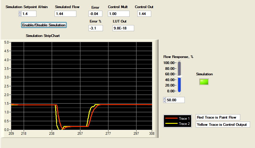
I wasn't particularly happy with the results of my simulations because of the large overshoot that appeared in some of the simulation runs. Here's a recent chart showing the overshoot.
The yellow trace is the control signal and the red trace is the Paint Flow response.
 |
| Control System Simulation, Stepping between 0.2 and 1.4 lbs/min for Flow Response of 10% per Step. |
I had assumed a low-pass response of my Flow control system, that is, I assumed a low-pass response to a step function control signal. In my simulations, I adjusted what I call the "Flow Response" so that the controller sampled at X% of the response time of the pump and flowmeter response. The low-pass difference equation that I used for my simulations is below with a 10% Flow Response value:
PFlow = 0.1*out + 0.9*PrevPFlow;
PrevPFlow = PFlow.
An obvious possible way to reduce the overshoot would be to limit the control output signal. But before I tried that, I decided to take a look at the 1989 IEEE Control Systems article Development of Fuzzy Algorithms for Servo Systems by Y.F. Li and C.C. Lau to see if I could learn how the authors were able to achieve such good results, zero overshoot for their Fuzzy control system simulations.
So I set about using the Fuzzy Rules and Terms that Li and Lau showed in their article and entered them into the fis file for the Octave Fuzzy Logic Toolkit, then computed the LUT. However, I was not able to obtain the same or similar LUT.
The LUT and Chart that resulted from my analysis of the Li and Lau Terms and Rules is shown below.
 |
| LUT and LUT Chart Computed From the Li and Lau Article Terms and Rules. |
Below is the LUT from the Li and Lau article and the LUT Chart that I produced from the LUT.
 |
| The LUT and LUT Chart from the Li and Lau Article. |
As you can see, the LUT and LUT Chart that I produced from the Terms and Rules of Li and Lau's article is quite different with large gaps and strange looking surfaces. So possibly the Rules listed in the article are incomplete or my computation of the LUT is somehow erroneous. Whatever, the reason, I could not duplicate Li and Lau's LUT.
Since I was not able to get a good LUT from the Li and Lau Terms and Rules, I next decided to insert their published LUT into my LW/CVI simulation code and run some simulations. Here is just one of the simulations, this for a paint flow pump and flowmeter "Flow Response" of 10% to compare with the chart of the simulation of my LUT, shown above.
 |
| Control System Simulation of the Li and Lau LUT , Stepping 0.2 to 1.4 lbs/min for Flow Response of 10% per Step. |
Compared to the simulation that I ran for the 10% Flow Response, the simulation of Li and Lau's LUT shows an even greater overshoot of the paint flow response signal. Other sampling rates showed responses similar to those for my LUT, reported in my last post.
I concluded that the Li and Lau Fuzzy Control system is quite similar to mine and the overshoot depends on the controller's sampling rate. That is, a high sampling rate compared to the open-loop system response will result in considerable overshoot and the excellent results reported in Li and Lau's article are the result of choosing the best controller sampling speed.
So the next step to try to reduce the overshoot in the simulations was to limit the output signal as I suggested above. As a test, I decided to limit the output signal to +25% of the Setpoint and ran the following simulations, showing a great improvement in the overshoot values.
 |
| Control System Simulation With a Limited Output, Stepping between 0.2 and 1.4 lbs/min for Flow Response setting of 10%. |
 |
| Control System Simulation With a Limited Output, Stepping between 0.2 and 1.4 lbs/min for Flow Response setting of 25%. |
 |
| Control System Simulation With a Limited Output, Stepping between 0.2 and 1.4 lbs/min for Flow Response setting of 25%. |
 |
| Control System Simulation With a Limited Output, Stepping between 0.2 and 1.4 lbs/min for Flow Response setting of 80%. |
Happily, limiting the output signal to +25% of the setpoint value can greatly reduce the overshoot in the simulations.
A point that I neglected to make is that I am doing only coarse control. Oftentimes two stage control is employed in Fuzzy Control Systems, a Coarse control and Fine control. However, it may not be necessary to control the paint flow that tightly. Only coarse control, as in my simulations, results in less than 10% error which is probably adequate.
My tentative conclusion is that Fuzzy control using my LUT and limiting the output signal to +25% of the Setpoint value will produce adequate control of the paint flow.
No comments:
Post a Comment